Engineering Bulletin: Universal Slide-In Contact with THM Solder Tail, Form-Fit Drop-In for Keystone 108-2
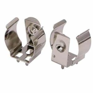
Securing multi-size cylindrical cells (AAA, AA, CR2) within high-vibration molded battery enclosures requires rigorous mechanical retention and rigid PCB pin coplanarity. The Jiatel JT-BC-108-2 functions as a high-reliability, 1:1 mechanical drop-in alternative for the industry-standard Keystone 108-2 contact. Engineered with lateral retention barbs for aggressive bite into plastic chassis ribs, this component also features a rigid 1.0mm downward solder tail. This dual-mounting architecture allows hardware engineers to lock the bracket securely into the enclosure while directly wave-soldering the tail to the FR4 board, eliminating secondary wire routing.
Verified Electro-Mechanical Parameters
| Target Cross-Reference | Form-Fit Mechanical Drop-In for Keystone 108-2 |
| Mounting Architecture | Slide-In (Barbed) + PCB Through-Hole Mount (THM) |
| Bracket Dimensions | 8.7mm (W) x 14.0mm (Base H) |
| Total Layout Height | 18.3mm (Including 1.0mm THM Pin) |
| Contact Deflection Clearance | 8.9mm Peak Protrusion |
| Base Metallurgy | Stainless Steel | Nickel Plated |
Target Deployments
- Industrial IoT: Wireless sensor nodes supporting mixed cell chemistry (CR2/AA).
- Security Systems: Door/window alarms utilizing high-tension battery retainers.
- Consumer Electronics: High-drain tactical enclosures with direct-to-board power routing.
Metallurgical Rigidity & Structural Retention
To prevent the contact from dislodging under the continuous axial compression of the battery cell, the JT-BC-108-2 is precision-stamped with aggressive lateral barbs. We engineered the main bracket from rigid stainless steel, guaranteeing absolute structural rigidity. The flexible leaf spring arm projects 8.9mm from the base to absorb length variations across AAA, AA, A, N, and CR2 cells. The entire assembly is finished with high-density nickel plating, maximizing wave solder wettability on the 1.0mm THM pin and defending against acidic electrolyte fluid leaks.
NPI Compartment Layout & SLA Directive
Enclosure integration demands strict adherence to molded plastic slot dimensions (8.7mm width) to ensure the lateral barbs bite securely without fracturing the chassis. Our engineering directive strictly prohibits the deployment of unverified digital mockups for compartment clearance checks. We execute structural seating audits and footprint validation exclusively through official [Technical Datasheets] and dimensionally controlled [2D Footprint Specs].
To confirm that our slide-in THM contact precisely matches your plastic compartment injection mold constraints and PCB drill holes, mobilize our Senior NPI Engineering Team. Submit your spatial constraints directly to our technical desk: NPI Engineering Queue. We guarantee the dispatch of matched, production-ready PDF drawings within 12 working hours of form submission.