Form-Fit Mechanical Replacement for High-Tolerance SMT Pins
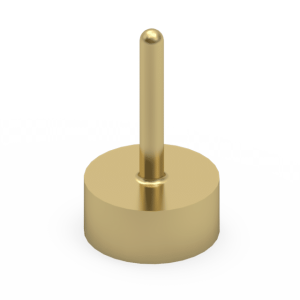
Electronic architectures involving modular enclosures, interchangeable docking interfaces, or parallel PCB stacks frequently encounter dimensional variations during mass assembly. The Jiatel 2.0×5.5mm series functions as a 1:1 mechanical drop-in alternative for high-tolerance legacy surface-mount pogo pins. By integrating a deep 1.5mm compression stroke, this SMT interconnect dynamically absorbs board-to-board co-planarity errors and mechanical shifts, preventing voltage cutoffs. The precision-machined flat base ensures maximum capillary action during reflow soldering, anchoring the connector securely against lateral shear forces.
Verified Technical Metrics
| Mechanical Profile | Ø 2.0mm Barrel | 5.5mm Resting Height |
| Deflection Stroke | 1.5mm Working Travel (High Tolerance) |
| Electrical Path Capacity | DC 12V / 1.0A to 1.65A Continuous Load |
| Contact Resistance | ≤ 25mΩ Initial Maximum |
| Thermal Profile Resilience | -40°C to +150°C Operational Range |
Target SMT Deployments
- Industrial Automation: Rugged sensor and ATE connections.
- Telecom Hardware: Modular base station interconnects.
- Medical DAQ: Interchangeable diagnostic probe interfaces.
- Automotive Systems: High-vibration infotainment routing.
Material Science Under Thermal Extremes
Accommodating a 1.5mm deep stroke within a 5.5mm overall height requires specialized internal spring calibration to prevent metal fatigue and signal degradation. The turned brass plunger and barrel are protected by a heavy gold-plated layer over a nickel diffusion barrier. This surface engineering hardens the contact point against friction during wide-tolerance matings and maintains mechanical integrity across 10,000 cycles. Explicitly tested to sustain performance up to +150°C, this high-temperature rating prevents pin seizing and survives rigorous SMT reflow profiles.
NPI Footprint Auditing & SMT Coplanarity
Surface-mounting interconnects subjected to variable compression forces requires strict control over pad alignment and vertical coplanarity to prevent angular tilt. We enforce tight CNC turning tolerances on the flat base to eliminate reflow placement errors. Our engineering directive strictly prohibits the deployment of unverified digital mockups. Footprint matching and pad clearance audits are processed exclusively using official [Technical Datasheets] and dimensionally verified [2D Footprint Specs].
To confirm that our 2.0×5.5mm SMT configuration integrates seamlessly into your board layout without causing solder wicking or pad shear, our Senior NPI Engineering Team executes comprehensive structural audits. To initiate a cross-reference evaluation, submit your SMT pad layout to our engineering desk: NPI Engineering Queue
SLA Commitment: Upon form submission to our NPI Engineering Queue, we guarantee the delivery of matched, production-ready PDF drawings within 12 working hours.