OBD-II (SAE J1962) Connector Pinout: 16-Pin Allocation & Type A vs B
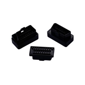
Quick answer: The OBD-II port is the 16-pin diagnostic interface defined by SAE J1962. Pin 16 supplies unswitched battery power, pins 4 and 5 are ground, pins 6 and 14 carry CAN High and CAN Low, and pin 7 carries K-Line. Five protocol families run over that shell: ISO 15765-4 (CAN), ISO 9141-2, ISO 14230-4 (KWP2000), and SAE J1850 PWM and VPW. Type A connectors are 12V passenger-car parts; Type B connectors are 24V heavy-duty parts with a different central keyway. The full cavity assignment is in the table below; the two ranges referenced throughout are OBD2 connectors and OBD wiring harnesses.
The OBD-II connector is the standard 16-pin diagnostic hardware interface governed by SAE J1962, deployed across passenger cars, light trucks, motorcycles and commercial vehicle platforms. For telematics device designers, fleet-tracking IoT developers and automotive harness engineers, choosing the correct sub-configuration is the baseline for keeping signal integrity between the scan tool and the vehicle’s ECU network.
Before optimising a BOM for a tracking or diagnostic product, these five engineering facts are what eliminate layout faults downstream. Jiatel maintains an audited drawing database so custom automotive connectivity can be specified without guesswork.
Fact 1: OBD-II Connectors Support 5 Distinct Communication Protocol Environments
The outer shell of the SAE J1962 port is globally identical. What changes underneath is the network architecture, and that decides which cavities must be populated and how fast the link can run.
- ISO 15765-4 (CAN bus): the dominant layout on modern vehicles, twin-wire differential data at up to 1 Mbit/s, carried on pins 6 and 14.
- ISO 9141-2 and ISO 14230-4 (KWP2000): single-wire asynchronous serial at 10.4 kbit/s, still common on older European and Asian platforms. Pin 7 carries the K-line, with pin 15 as the L-line handshake on ECUs that require it.
- SAE J1850 PWM and VPW: legacy pulse-width modulation, largely Ford and GM platforms. Pin 2 carries the bus, with pin 10 as the second half of the PWM pair.
Judgment: if the vehicles you serve span more than one protocol family, populate the full 16-cavity shell once instead of stocking a separate part number per protocol — the OBD2 connector housings range is built so all five families share one housing platform.
Fact 2: 16-Pin Allocation — Standard Channels vs. Manufacturer Custom Tracks
Only nine of the sixteen cavities are actually assigned by SAE J1962. The other seven are manufacturer discretion, and that is where most custom harness projects get into trouble.
| Pin | SAE J1962 assignment | Electrical role | What it changes in a custom build |
|---|---|---|---|
| 1 | Manufacturer discretion | Reserved | Leave empty unless the OEM spec names it |
| 2 | SAE J1850 Bus+ | Legacy PWM / VPW data | Populate only for pre-CAN Ford and GM platforms |
| 3 | Manufacturer discretion | Reserved | Repurposed as an Ethernet pair on DoIP vehicles |
| 4 | Chassis ground | Body return | Bond to chassis; never merge with pin 5 |
| 5 | Signal ground | Logic reference | Keep a separate return to avoid ground loops |
| 6 | CAN High | ISO 15765-4 differential + | Mandatory on any CAN-era vehicle |
| 7 | ISO 9141-2 / KWP2000 K-line | Single-wire serial | Required for older European and Asian ECUs |
| 8 | Manufacturer discretion | Reserved | OEM anti-theft and auxiliary circuits |
| 9 | Manufacturer discretion | Reserved | OEM anti-theft and auxiliary circuits |
| 10 | SAE J1850 Bus− | Legacy PWM data − | Second half of the PWM pair; unused on VPW |
| 11 | Manufacturer discretion | Reserved | Repurposed as an Ethernet pair on DoIP vehicles |
| 12 | Manufacturer discretion | Reserved | Repurposed as an Ethernet pair on DoIP vehicles |
| 13 | Manufacturer discretion | Reserved | Repurposed as an Ethernet pair on DoIP vehicles |
| 14 | CAN Low | ISO 15765-4 differential − | Route as a matched pair with pin 6 |
| 15 | ISO 9141-2 / KWP2000 L-line | Handshake return | Often omitted; some older ECUs need it to initialise |
| 16 | Battery positive | Unswitched +12V (Type A) / +24V (Type B) | Always live — fuse inside the device, not vehicle-side |
Table: SAE J1962 16-pin allocation. Pins 1, 3, 8, 9, 11, 12 and 13 are reserved for manufacturer use; on DoIP (Ethernet) vehicles several of them carry Ethernet pairs instead of auxiliary circuits.
Three consequences follow from that split. Power and ground must not share a return path — merging pin 4 and pin 5 is the most common cause of ground-loop noise in aftermarket devices. The CAN pair has to be routed as a matched differential pair, or the link starts dropping frames at length. And the discretionary cavities are where OEMs hang anti-theft loops and auxiliary subsystems, so they need their own shielding rather than a shared drain wire.
Judgment: if your pinout uses any of the seven reserved cavities, the cable is a custom design even when the connector itself is standard — specify it as an OBD wiring harness with a documented per-cavity allocation instead of adapting an off-the-shelf lead.
Fact 3: Structural Differentiation — Type A (12V) vs. Type B (24V) Standards
OBD-II deployments split by operating voltage and by the physical keyway, and the split exists to stop a 24V truck being probed with a tool built for a 12V car.
- Type A: rated for 12V supply and roughly 500 kbit/s data, engineered for sedans, light crossovers and consumer passenger cars.
- Type B: built for heavy and medium-duty transport — buses, logistics trucks and industrial equipment — carrying a 24V supply with an altered central keyway that physically blocks incorrect insertion.
Judgment: a 24V fleet programme needs Type B tooling from the start; retrofitting a Type A housing with a higher-rated contact will still fail the keyway, so specify Type A and Type B OBD2 connectors as two separate part numbers with their own drawings.
Fact 4: Base Plating Thickness & Polymer Compounds Enforce Decadal Lifecycles
Most low-cost OBD plugs fail at the terminal, not the housing: localised oxidation on thin plating, then plastic creep around the cavity under closed-cabin heat.
- Plating stack: deep nickel underplate topped with hard gold keeps contact resistance stable past 10,000 mating cycles. Thin flash gold is what produces the intermittent no-communication fault that only appears in summer.
- Housing compound: glass-filled PBT or high-impact ABS rated to UL94V-0 resists pin shift around the always-live battery cavity, which is the one carrying current when the vehicle is parked.
Judgment: if your lifecycle target is above 10,000 mating cycles, the plating stack has to be specified rather than inherited from a catalogue part — request a plating and polymer review before tooling is cut, because the underplate thickness cannot be added after moulding.
Fact 5: Integrated Custom Overmolding Outperforms Manual Cable Rework
Hand-soldering a J1962 terminal block and wrapping it in heat-shrink creates a fatigue point directly behind the connector, exactly where a dashboard cavity flexes. Factory overmolding replaces that joint with vulcanised strain relief and a gas-tight internal seal, which is also what reclaims space in narrow dashboard enclosures.
Automated assembly lines handle the variants that show up in real programmes: OBD2-to-open-wire pigtails, right-angle and L-shaped extensions for tight installs, and dual Y-splitter networks for fleet logistics transponders.
Judgment: if the cable has to survive vehicle motion rather than sit on a bench, overmolding is a process decision that cannot be retrofitted to a hand-built lead — choose overmolded pigtail assemblies at the design stage.
When to Buy a Harness Instead of Parts
Buying the connector is the cheap half of the job. The real cost sits in termination, strain relief and test — and those are process costs, not part costs. Four conditions mean you should stop buying components and buy a finished assembly:
- Rework has become a line item. Hand-crimping sixteen cavities and finding a lifted terminal after potting costs more than the connector did. If you are already counting rework hours, the assembly is cheaper.
- The cable has to move. A dashboard cavity sees vibration and thermal cycling; a soldered joint under heat-shrink is a fatigue point by construction. Overmolded strain relief is a process, not a part you can add later.
- You need pinout proof per unit. A purchased assembly ships with a continuity and pinout record. Hand-built cables are verified by whoever built them, and that does not survive an audit.
- You are scaling past prototype. Unit labour does not fall with volume the way tooling cost does, so at some quantity the arithmetic flips. Ask for the comparison before committing to in-house build.
If two or more of those apply, buy the assembly. Five inputs make the quote usable on the first pass: pin allocation per cavity, wire gauge and insulation type, overall length and tolerance, keyway type (A or B), and the acceptance test you will actually run.
Judgment: for teams that have already lost a batch to hand rework, the OBD wiring harnesses line covers adapter, splitter and open-wire builds on the same terminals used in the connector range.
BOM Optimization: Transponder Code Decoding Integration
The diagnostic hardware connected through a custom cable assembly decodes raw Diagnostic Trouble Codes (DTC) streamed over the vehicle bus. These five-character codes map faults across four domains: Powertrain (P), Network and Vehicle Integration (U), Body (B) and Chassis (C). Maintaining a continuous low-impedance connection is what prevents dropped packets during code clearing or live sensor logging.
Whether the tracking node is an app-dependent mobile adapter for casual fleet logs or a standalone professional scanner in a workshop, terminal coplanarity is what keeps the board-level validation from failing.
Standard Drawing Vault & Senior NPI Engineering Queue
Automated wire termination and custom vehicle pinning demand micrometre-level accuracy. To protect engineering version control and keep client designs out of public indexes, Jiatel does not publish open 3D model downloads; audited mass-production-ready drawings are released through the engineering queue instead.
Whether the programme is a quick evaluation batch or a production delivery inside two weeks, the technical sheets are ready for review. Send your trace logic and clearance constraints and the Senior NPI Engineering Team will cross-audit the parameters:
SLA Delivery Commitment: Jiatel officially guarantees that checked, production-ready [Technical Datasheets] and [2D Footprint Specs] matching your precise pinning allocation will be dispatched in verified PDF format within 12 hours after your application enters our NPI Engineering Queue.
OBD wiring harnessesAdapters, splitters and open-wire builds on J1962 terminals
Overmolded pigtail assembliesSealed strain relief for cables that see vehicle motion

Frequently Asked Questions
What is the OBD-II connector standard?
OBD-II is the 16-pin diagnostic interface defined by SAE J1962. The outer shell is globally unified, but the network architecture behind it changes between vehicle makes.
Which pins supply power and ground?
Pins 4 and 5 are the chassis and electrical reference grounds. Pin 16 carries an unswitched +12V/24V always-on battery feed.
Which pins carry CAN High and CAN Low?
Pin 6 is CAN High and Pin 14 is CAN Low. Pin 7 carries the K-Line used by older serial protocols.
Which communication protocols does OBD-II use?
Five are in scope: ISO 15765-4 (CAN bus), ISO 9141-2 and ISO 14230-4 (KWP2000), plus the legacy SAE J1850 PWM and VPW variants used mainly by Ford and GM platforms.
What is the difference between Type A and Type B OBD-II connectors?
Type A is rated for 12V supplies and roughly 500 kbps data, and is used on passenger cars and light crossovers. Type B is built for heavy and medium-duty transport on a 24V threshold, and uses an altered central keyway that blocks incorrect insertion.
Can the reserved pins be used for custom circuits?
The pinout divides the 16 terminal pathways into fixed roles. Pins 1, 3, 8, 9, 11, 12 and 13 are reserved and are customised by OEMs for anti-theft loops or auxiliary subsystems, so they need proper shielding design.
Need this built as a finished assembly?
We build custom OBD pigtail cables to your pinout — 16-pin J1962, overmolded to IP67 or open-ended, with DFM feedback and 2D drawings back within 12 hours.
From pinout to finished harness
You already have the 16-pin map. We crimp it: SAE J1962 Type A / Type B housings, custom lengths, open or overmolded, built to your pinout.