Engineering Bulletin: Slide-In Positive Integration with Solder Ear
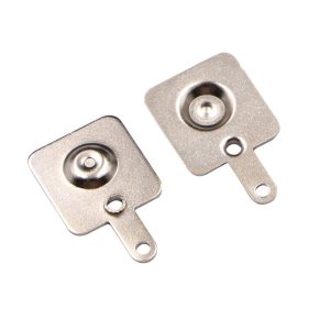
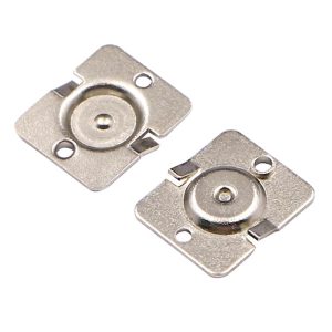
Securing the positive terminal in molded battery enclosures requires precise dimple protrusion and robust wire routing capabilities. The Jiatel JT-BC-AA-KS5219 functions as a high-reliability, 1:1 mechanical drop-in alternative for the industry-standard Keystone 5219 contact. Engineered as the perfect mating counterpart to the 5220 negative spring, this component features an identical 11.20×11.99mm bracket footprint with an extended solder ear (lug). This symmetrical slide-in architecture allows hardware engineers to design uniform plastic chassis slots while providing a dedicated, heat-efficient soldering point for heavy-gauge wire harnesses.
Verified Electro-Mechanical Parameters
| Target Cross-Reference | Keystone 5219 Equivalent (Positive) |
| Mating Component | JT-BC-5220 (Negative Spring Contact) |
| Bracket Dimensions | 11.20±0.25mm (W) x 11.99±0.25mm (H) |
| Total Layout Height | 18.34±0.25mm (Down to Solder Ear) |
| Positive Dimple Height | 1.45±0.20mm Protrusion |
| Base Metallurgy | T=0.50mm Steel | Full Nickel Electroplating |
Target Deployments
- Industrial Telematics: Ruggedized barcode scanners and testing meters.
- Medical Diagnostics: Portable patient monitoring tools (CR2/AA).
- Consumer Electronics: High-drain enclosures with wire-harness routing.
- Smart Peripherals: IoT sensors utilizing standard cylindrical cells.
Metallurgical Rigidity & Dimple Mechanics
To ensure proper polarity engagement and minimal contact resistance, the JT-BC-5219 features a precision-stamped solid dimple protruding at 1.45±0.20mm. The main bracket and integrated 3.00mm wide solder ear are stamped from rigid T=0.50mm steel. This gauge is critical to prevent plate warping when subjected to the continuous axial compression forces generated by the opposing negative spring. The entire assembly is sealed with a high-density nickel plating, ensuring rapid heat transfer during manual wire soldering while maximizing oxidation defense against acidic electrolyte fluid leaks.
NPI Compartment Layout & SLA Directive
Automated assembly lines and molded plastic enclosures demand absolute mechanical precision to prevent battery misalignment or solder ear interference. Our engineering directive strictly prohibits the deployment of unverified 3D digital mockups for compartment clearance checks. We execute structural seating audits and footprint validation exclusively through official [Technical Datasheets] and dimensionally controlled [2D Footprint Specs].
To confirm that our slide-in positive contact matches your plastic compartment injection mold slots (11.20mm width requirement) and accommodates the 18.34mm total vertical clearance, deploy our Senior NPI Engineering Team. Submit your spatial constraints directly to our technical desk: NPI Engineering Queue. We guarantee the dispatch of matched, production-ready PDF drawings within 12 working hours.