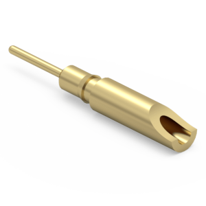
Seamless Cross-Reference Integration for 1140 Solder Cup Pins
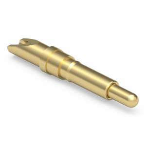
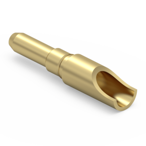
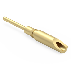
Designed to resolve lead-time bottlenecks for rugged wire-to-board interconnects, the Jiatel 1140-compatible series delivers a 1:1 mechanical drop-in solution for legacy terminal pin layouts. By maintaining an exact solder cup geometry capable of housing up to 20 AWG stranded wire, we ensure a gas-tight, high-current connection that significantly outperforms standard spring pins in high-vibration environments. The precision-turned brass alloy shell is plated with a standard 10μ” gold over a nickel barrier, securing absolute solderability and zero-defect signal transfer across a -55°C to +125°C thermal range.
Verified Technical Metrics
| Wire Termination Capacity | Solder Cup (Accepts up to 20 AWG) |
| Mounting Style 1: Press-Fit | Requires 0.057″ (1.45mm) PCB Hole |
| Mounting Style 2: Through-Hole | Requires 0.044″ (1.12mm) PCB Hole |
| Base Material | Precision Machined Brass Alloy (C3604) |
| Plating Specification | 10μ” Gold over Nickel |
Target Solder Cup Applications
- Industrial Automation: Heavy-duty wire anchoring.
- Medical DAQ: High-reliability cable-to-board interfaces.
- Military & Aerospace: High-vibration wire termination.
- Power Delivery: Custom high-current harness modules.

Standardized BOM Cross-Reference
To streamline your procurement cycle, evaluate the specifications below. These standard Jiatel part numbers are engineered to directly replace the corresponding legacy models:
| Jiatel Part Number | Alternative to Mill-Max | Shell Plating | RoHS Status |
|---|---|---|---|
| 1140-0-01-15-00-00-03-0 | 1140-0-01-15-00-00-03-0 | 10μ” Gold | Compliant |
| 1140-0-01-01-00-00-03-0 | 1140-0-01-01-00-00-03-0 | Matte Tin | Compliant |
| 1140-0-01-80-00-00-03-0 | 1140-0-01-80-00-00-03-0 | Tin-Lead (Non-RoHS) | Non-Compliant |
NPI Engineering & Layout Validation
Securing a terminal pin via press-fit (NPTH) or traditional wave soldering requires absolute dimensional control over the knurled shank and tail geometry. We mitigate PCB fracturing and solder wicking risks by enforcing strict CNC turning tolerances. Our engineering directive strictly prohibits the use of unverified digital mockups. We execute footprint validation exclusively through official [Technical Datasheets] and dimensionally verified [2D Footprint Specs].
To confirm that our 1140 series terminals align flawlessly with your 1.45mm (press-fit) or 1.12mm (through-hole) layout, engage our Senior NPI Engineering Team. For specialized plating thickness requirements (from 1μ” up to 30μ”) to optimize project budgets, route your parameters directly to our desk: Request Engineering Support
SLA Commitment: Upon form submission to our NPI Engineering Queue, we guarantee the dispatch of matched, production-ready PDF drawings within 12 working hours.