Engineering Brief: 1.8×2.5mm Micro SMT Interconnect
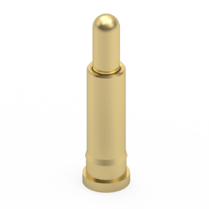
High-density electronics, including TWS earbuds, AR/VR headsets, and biometric wearables, dictate stringent volumetric constraints. The Jiatel 1.8×2.5mm micro pogo pin series provides a reliable mechanical cross-reference for ultra-small legacy SMT contacts. By restricting the maximum seating height to just 2.5mm, we enable hardware engineers to reduce the overall device profile. The precise 0.5mm working stroke is calibrated to absorb micro-level PCB co-planarity variances without applying excessive upward force against thin device enclosures.
1.0 Validated Operational Parameters
| Parameter | Specification / Limit |
|---|---|
| Dimensional Envelope | 1.8mm Diameter | 2.5mm Overall Height |
| Mechanical Stroke | 0.5mm Working Travel |
| Electrical Path Capacity | DC 12V | 0.5A – 1.0A Continuous |
| Maximum Contact Resistance | 50mΩ (Calibrated for micro-pins) |
| Metallurgy | Precision-Turned Brass | Gold over Nickel Plating |
| Thermal Endurance | -40°C to +150°C |
2.0 Target Micro-SMT Deployments
This ultra-compact SMT profile is actively deployed in architectures where standard 4.0mm+ pins cause structural interference:
- Wearable Biometrics: Smartwatch charging nodes and continuous health monitoring sensor contacts.
- Consumer Audio: TWS (True Wireless Stereo) earbud charging cases.
- Micro IoT Modules: Space-saving power interconnects for remote RF transceivers.
- Medical Portables: Disposable diagnostic sensor junctions.
3.0 NPI Footprint Verification & SLA Directive
Surface-mounting a 2.5mm height micro-component demands exact pad alignment to prevent solder wicking and component float during automated reflow. To mitigate integration risks, our manufacturing protocol strictly prohibits the distribution of unverified digital mockups. We mandate that all footprint audits and clearance checks be executed exclusively against official [Technical Datasheets] and dimensionally controlled [2D Footprint Specs].
To ensure this 1.8×2.5mm micro pogo pin is a 1:1 match for your existing PCB land pattern, engage our Senior NPI Engineering Team. Submit your structural constraints to our technical desk: NPI Engineering Queue
SLA Commitment: Upon successful submission of your requirements to our NPI Engineering Queue, we guarantee the dispatch of matched, production-ready PDF drawings within 12 working hours.