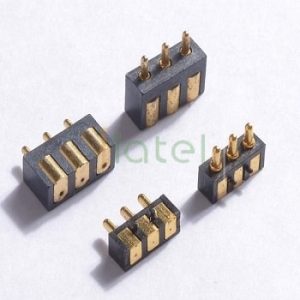
Mechanical Architecture: Flat-Barrel Side-Mounted SMT
Modern slimline enclosures frequently lack the vertical clearance required for top-entry spring contacts. The Jiatel 2.0×6.2mm series resolves this by acting as a 1:1 mechanical alternative for standard side-mounted pogo pins. Unlike traditional right-angle pins that require bending the tail, this interconnect utilizes a straight barrel with a precision-milled flat surface. By orienting the flat barrel parallel to the PCB, mating forces are directed horizontally. The calibrated 0.8mm compression stroke absorbs lateral tolerances, ensuring an unbroken 2.0A electrical path without adding any Z-axis overhead to the PCB stack-up.
1.0 Electro-Mechanical Specifications
| Parameter | Engineering Limit |
|---|---|
| Dimensional Footprint | Ø 2.0mm (Milled Flat Base) | 6.2mm Overall Length |
| Kinematic Deflection | 0.8mm Working Travel |
| Electrical Path Capacity | DC 12V | 1.0A to 2.0A Continuous Load |
| Dynamic Impedance | ≤ 30mΩ Initial Maximum Resistance |
| Thermal Endurance | -40°C to +150°C | SMT Reflow Compatible |
| Base Metallurgy | Turned Brass | Heavy Gold over Nickel Plating |
Anti-Roll Geometry & Lateral Shear Resistance
Side-mounted connectors are subjected to continuous lateral shear forces during the mating cycle. To prevent solder joint fatigue and component rolling during automated pick-and-place, the 2.0mm barrel is engineered with a precision-milled flat mounting footprint. This geometry maximizes the capillary action and reflow solder fillet area, anchoring the connector securely to the PCB. The heavy gold-plated contact surface ensures that dynamic resistance remains below 30mΩ across 10,000+ horizontal mating cycles, surviving high-vibration deployments without signal degradation.
NPI Layout Audit & SLA Directive
Horizontal surface-mounting demands absolute precision in pad alignment to counter lateral insertion forces. Our engineering directive strictly prohibits the deployment of unverified 3D digital mockups. We execute structural matching and footprint validation exclusively through official [Technical Datasheets] and dimensionally controlled [2D Footprint Specs].
To confirm that this 2.0×6.2mm flat-barrel configuration integrates flawlessly into your board layout, submit your pad constraints directly to our technical desk: NPI Engineering Queue. We guarantee the dispatch of matched, production-ready PDF drawings within 12 working hours.