Overmolded Cable Assembly Guide: What It Is and Why You Need It
I. What is an Overmolded Cable Assembly?
An overmolded cable assembly refers to a technique in the cable manufacturing field that combines innovation and practicality. Specifically, through the injection molding process, liquid plastic is precisely and evenly coated onto specific parts of the cable, such as connectors, branching points, or sections that require additional safeguarding. Once the plastic cools and solidifies, it becomes an integral part of the cable. Figuratively speaking, it’s like dressing the cable in a custom-made “protective armor” that not only fits tightly but can also take on various intricate and elaborate shapes according to different design requirements.
In today’s electronics realm, cables play a crucial role as the “arteries” for signal and power transmission. The stability and reliability of their connections are of paramount importance. Overmolded cable assemblies, with their unique strengths, have become indispensable components in numerous high-end electronic devices, industrial automation systems, and automotive electronic architectures. For instance, inside high-speed computer servers where complex wiring is connected by overmolded cable assemblies to ensure the rapid transfer of data, or in the harsh environment of a car engine compartment where heat-resistant and vibration-proof overmolded cables guarantee stable communication between the electronic control system and various components, they vividly demonstrate their essential position. They are like unsung heroes, silently facilitating the efficient operation of the modern electronics world and enabling different devices to function precisely and stably.
II. What are the Benefits of Using Overmolded Cable Assemblies?
(1) Superior Protection of Mechanical Properties
Overmolded cable assemblies provide a formidable mechanical protection shield for cables. When external forces pull on the cable, the overmolded layer, thanks to its tough material properties, can evenly distribute the pulling force, thus preventing stress concentration on the internal conductors of the cable and effectively reducing the risk of conductor breakage. For example, in an industrial automation production line, the connection cables between frequently moving robotic arms and control units are highly susceptible to damage to the conductors under long-term and repeated pulling if ordinary cables are used. However, overmolded cable assemblies can effortlessly withstand such situations, ensuring the stable operation of the production line.
Moreover, when faced with bending and squeezing, the overmolded layer serves as a buffer and support. When the cable needs to navigate around obstacles or be routed in a narrow space, the overmolded layer can deform moderately to absorb the bending stress, preventing the insulation layer from cracking and the conductor core from breaking. In scenarios where heavy objects exert pressure, like when cables in a computer room are squeezed by equipment, the high-strength compressive capacity of the overmolded layer keeps the internal structure of the cable intact, significantly prolonging the cable’s service life and ensuring the continuous transmission of signals and power.
(2) Outstanding Guarantee of Electrical Properties
Overmolded cable assemblies have a remarkable impact on enhancing electrical performance. Firstly, they create a stable environment for signal transmission. By tightly enveloping the cable, they reduce the influence of external electromagnetic interference on the signal, ensuring the accuracy of data transmission. In the case of high-speed computer network cabling, even the slightest electromagnetic interference can lead to data packet loss and transmission errors. The shielding properties of overmolded cable assemblies can effectively block these interferences, guaranteeing the high-speed and stable operation of the network.
Secondly, in the domain of high-frequency transmission, their advantage in controlling signal attenuation is quite evident. Compared with ordinary cables, overmolded cable assemblies can precisely maintain the strength and integrity of the signal, meeting the stringent requirements for high-frequency and high-speed signal transmission in applications such as 5G base stations and satellite communications. Relevant test data shows that within a specific frequency range, the signal attenuation rate of ordinary cables can reach 10% – 15%, while that of overmolded cable assemblies can be controlled within 5%, laying a solid foundation for the precise operation of high-end electronic equipment.
(3) High Environmental Adaptability
The environmental adaptability of overmolded cable assemblies is a significant highlight. Their waterproof, dustproof, and moisture-proof characteristics enable them to perform admirably in humid and dusty environments. For outdoor electronic billboards, regardless of heavy rain or sandstorms, the overmolded layer can effectively seal out water and dust, ensuring the normal operation of the internal circuits. In underground pipe corridors, mines, and other locations with high humidity and a large amount of dust, they can effectively prevent short circuits, discharges, and other problems caused by water vapor erosion and dust accumulation.
Furthermore, their high-temperature and corrosion-resistant properties allow them to brave harsh working conditions. In metallurgical factories, the cables near high-temperature furnaces must endure baking at extremely high temperatures (over a thousand degrees Celsius) as well as the corrosion of corrosive gases. Overmolded cable assemblies, relying on special high-temperature and corrosion-resistant materials, can operate stably for extended periods, providing reliable support for the continuity of industrial production and greatly expanding the application scenarios of cables. They are undoubtedly the top choice for electrical connections in complex environments.
III. Customization Options for Overmolded Cable Assemblies
(1) Customization of Circuit Size and Cable Length
In the diverse landscape of today’s electronic devices and industrial applications, the customization options for the circuit size and cable length of overmolded cable assemblies exhibit high practicality.
In terms of circuit complexity, whether it’s a simple point-to-point connection or a complex circuit architecture with multiple branches and hierarchical levels, customized overmolded cable assemblies can accurately fulfill the requirements. Take consumer electronic products as an example. For portable smart speakers, their internal circuits are relatively simple. By customizing short and delicate overmolded cables, efficient connections among the battery, motherboard, and speakers can be achieved within a limited space. This not only meets the signal transmission needs but also avoids a messy wiring layout, enhancing the product’s portability and aesthetics.
In large industrial automation control systems, when dealing with the interaction between complex control units, sensor groups, and actuators, customized overmolded cables can be designed according to the detailed circuit blueprint to construct a “neural network” with multiple signal and power transmission paths, ensuring the orderly operation of the entire system.
The customization of cable length is also tailored to the unique layout requirements of various devices. In the medical equipment field, for a precise magnetic resonance imaging (MRI) machine, its key internal components are distributed in a specific mechanical structure, imposing strict requirements on the length of the connection cables. Customized overmolded cable assemblies with the appropriate length can not only ensure the stable transmission of signals in a strong magnetic field environment but also avoid the risks associated with overly long cables, such as entanglement and signal attenuation, as well as the connection tension problems caused by overly short cables. This provides a solid guarantee for the high-precision operation of the equipment.
Similarly, in the aerospace field, the compact and functionally diverse cabin layouts of spacecraft demand that the cables connecting different modules be of precisely customized lengths. Overmolded cable assemblies, with this characteristic, can still reliably transmit commands and data in extreme environments, contributing to humanity’s exploration of the universe.
(2) Customization of Connector Types and Interfaces
Overmolded cable assemblies can be adapted to a wide variety of connector types, facilitating seamless connections between different devices. Common connector types include circular connectors, rectangular connectors, and board-to-board connectors, each with its own specific application scenarios.
Circular connectors, renowned for their excellent sealing and mechanical stability, are widely used in fields that demand extremely high reliability, such as military equipment and aerospace. For instance, in the avionics system of a fighter jet, various sensors, control systems, and onboard computers are connected by overmolded cable assemblies equipped with circular connectors. This ensures the reliable transmission of data and power under high-speed flight, intense vibration, and complex electromagnetic environments.
Rectangular connectors, with their multi-pin arrangement and the convenience of being easily plugged and unplugged, are highly favored in industrial control cabinets and communication base station equipment. They allow technicians to quickly install, maintain, and replace components, significantly improving work efficiency.
The diversity of interface standards is also a key aspect of customization. From the common USB and HDMI interfaces that meet the rapid data interaction requirements of consumer electronic products to the RS232 and RS485 serial ports in the industrial field that ensure long-distance and anti-interference communication capabilities, overmolded cable assemblies can be precisely adapted to these different interfaces. In the in-car infotainment system of a smart car, one end of the customized overmolded cable is designed with a high-speed CAN bus interface that complies with automotive electronic standards and is connected to the vehicle’s electronic control unit (ECU). The other end is adapted to consumer-level interfaces such as USB and AUX of the multimedia entertainment system, enabling the comprehensive integration of the car’s intelligent functions. This allows drivers to enjoy convenient in-car entertainment while also relying on precise vehicle control to enhance driving safety and comfort.
(3) Customization of Material Selection
The material selection for overmolded cable assemblies is rich and diverse, providing a solid foundation for meeting different usage environments and performance requirements.
In terms of insulating materials, polyvinyl chloride (PVC) is widely used in the internal connection wires of ordinary civilian electrical equipment, such as household appliances, due to its cost-effectiveness and good insulating properties. It effectively prevents the risk of electric leakage, ensuring the safety of users’ electricity consumption. For scenarios that require higher insulation strength and aging resistance, like the connection cables between outdoor power transformers and distribution boxes, cross-linked polyethylene (XLPE) is the preferred material. It can maintain stable insulation performance in outdoor environments with long-term ultraviolet irradiation and significant temperature variations, ensuring the reliable transmission of power.
Wear-resistant materials are of great importance in industrial production environments. The overmolded layer made of polyurethane (PU) endows the cable with excellent wear resistance. In the working conditions of frequent movement and friction in automated production lines, it protects the internal structure of the cable from damage, extends the cable’s service life, and reduces equipment maintenance costs. In some special mining equipment, where cables not only need to withstand the scratching of ores but also resist the corrosion of corrosive gases and liquids in the mine, fluoroplastics (such as polytetrafluoroethylene PTFE) are used as injection molding materials. Thanks to their outstanding chemical inertness, high-temperature resistance, and superior wear resistance, they ensure the stable operation of cables in the harsh underground environment, safeguarding the continuity of mining production.
IV. How is an Overmolded Cable Assembly Manufactured?
(1) Preparation of Raw Materials
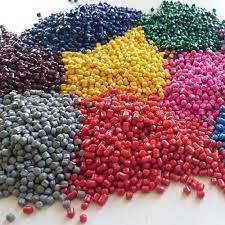
The production of overmolded cable assemblies begins with the careful selection of raw materials. The core raw materials include plastic pellets, additives, and various auxiliaries, and the quality of these materials directly affects the performance of the final product.
When it comes to plastic pellets, polyvinyl chloride (PVC) is commonly used in the manufacturing of cable assemblies for conventional electrical environments because of its good insulation, corrosion resistance, and relatively low cost. However, for applications with strict requirements for high-temperature tolerance, such as the cables around a car engine compartment, high-performance plastics like polyetheretherketone (PEEK) are chosen. PEEK can operate stably in high-temperature environments exceeding 200°C, ensuring reliable circuit connections.
Throughout the raw material control process, strict quality control procedures are implemented. Each batch of plastic pellets entering the factory must undergo spectral analysis testing to ensure material purity and prevent the incorporation of impurities. Any impurities could potentially affect the mechanical strength and electrical insulation performance of the product after injection molding. The addition ratio of additives is precisely controlled to the milligram level. Through automated weighing and mixing equipment, the uniform dispersion of each component is ensured, laying a solid foundation for subsequent stable production.
(2) Design and Manufacture of Injection Molding Molds
The mold is the “soul” of the injection molding process, and the precision of its design and the quality of its manufacturing are decisive factors in determining the quality of cable assemblies.
Starting from the drafting of the design blueprint, engineers use advanced CAD/CAM software for simulation modeling based on the precise dimensions of the cable, its complex connection structure, and the expected thickness of the overmolded layer. For example, when designing a mold for a multi-branch industrial control cable assembly, the flow path direction at the branching points needs to be carefully planned to ensure that the plastic melt can evenly and smoothly fill every tiny corner, avoiding local material shortages or stress concentrations. At the same time, considering the convenience of product demolding, the draft angle of the mold is designed to be within the range of 0.5° – 2° to prevent the product from sticking to the mold after molding and damaging its appearance and structure.
The manufacturing process of the mold is a rigorous test of process precision. The mold cavity is processed using high-precision electrical discharge machining (EDM) technology, combined with ultra-precision grinding and polishing processes. As a result, the surface roughness of the cavity can reach Ra0.1 – Ra0.2μm, close to a mirror-like finish. This not only ensures the smooth appearance of the injection molded product but also reduces the flow resistance of the plastic melt, improving the molding efficiency. The cooling system of the mold is optimized through simulating the heat conduction process, and a conformal cooling channel design is adopted. This ensures that the cooling rate of each part of the mold is uniform, effectively reducing the warping and deformation problems of the product caused by uneven cooling, providing a solid guarantee for large-scale and high-quality production.
(3) Injection Molding Process
The injection molding process is a delicate and coordinated operation where every step is crucial and any deviation can affect the quality of the final product.
In the initial plasticizing stage, plastic pellets are gradually heated to a molten state under the rotational and shearing action of the screw in the injection molding machine barrel. The precise control of the barrel temperature is essential. Taking the injection molding of common polyethylene (PE) as an example, the temperature of the front section of the barrel needs to be stably maintained at 180°C – 220°C, the middle section at 160°C – 190°C, and the rear section at 140°C – 170°C. The temperature differences in different regions ensure the uniform plasticizing of the plastic and prevent local overheating decomposition or insufficient plasticizing.
During the melt filling process, the coordinated control of injection pressure and speed is the key. High pressure and high speed can quickly fill the mold cavity, but it may lead to problems such as trapped air and flash. On the other hand, low pressure and low speed may result in incomplete filling. For example, when manufacturing injection molded cable assemblies for small consumer electronics, the initial filling is carried out at low pressure and low speed (pressure 30 – 50MPa, speed 10 – 20mm/s) to steadily push the melt to about 80% of the cavity. Then, it switches to high pressure (80 – 120MPa) and medium speed (30 – 50mm/s) to ensure that the melt completely fills the cavity and forms a dense product.
In the holding pressure stage, based on the product size and plastic characteristics, the holding pressure and time are precisely set to continuously supply the plastic melt to the cavity, compensating for cooling shrinkage and preventing product shrinkage holes and depressions. Finally, after cooling and solidification, the mold is opened, and with the help of the ejection mechanism, a high-quality overmolded cable assembly is produced.
(4) Post-treatment and Quality Inspection
Once the product is removed from the mold, it is only the first step towards becoming a finished product. Subsequent meticulous post-treatment is indispensable.
The edges of the newly demolded cable assemblies often have burrs and flash that need to be carefully removed through deburring processes. Precision grinding equipment or chemical etching methods can be used to smooth the edges of the parts. For cable assemblies used in medical and optical equipment with extremely high surface requirements, additional processes such as micro-grinding and ultrasonic cleaning are also employed to thoroughly remove fine particles and oil stains on the surface. This ensures that the product cleanliness meets the cleanroom standard and avoids interfering with the operation of precision equipment.
The quality inspection process is like a strict “judgment tribunal” that covers all aspects from appearance inspection to performance testing. In terms of appearance, high-definition optical inspection equipment is used to check the dimensional accuracy and surface defects of the product one by one. The dimensional tolerance is controlled within ±0.05mm to ensure that it matches the design drawing precisely. During the electrical performance test, the cable assembly is placed in professional withstand voltage testers and insulation resistance testers to simulate the actual working voltage and test the insulation performance. The insulation resistance value is required to be no less than 100MΩ even in a humid environment, and the withstand voltage should exceed the rated working voltage by 2 – 3 times to ensure safe use. The mechanical performance test simulates the stress conditions of the cable under different working conditions through repeated bending, stretching, and torsion tests. For example, a high-quality overmolded cable assembly should be able to withstand more than 10,000 bends without any signs of conductor breakage or insulation layer damage. Through comprehensive quality control, reliable overmolded cable assembly products are delivered to the market.
V. What’s in a Mold?
The mold, as the core equipment in the injection molding process, has a complex and precise structure where each component works in harmony to produce a perfect overmolded cable assembly.
The cavity, which can be regarded as the “female mold”, is the key space where the plastic melt finally takes shape. It accurately replicates the external contour of the product, from the tiniest details to the overall shape, strictly following the design blueprint. The corresponding core, similar to the “male mold”, is responsible for shaping the internal cavities and holes of the product, ensuring the precise formation of the internal structure of the cable assembly. For instance, at the connection points of multi-core cables, the wire grooves formed by the core can precisely accommodate the conductors, ensuring the orderly arrangement of the circuits.
The gate, although small in size, plays a crucial role as it controls the “flow valve” through which the plastic melt enters the cavity. Different types of gates, such as pin-point gates and submarine gates, have their own unique features. The pin-point gate is like a fine dropper that can inject the melt precisely and slowly without affecting the appearance of the product. It is suitable for cable assemblies of small electronic devices with strict appearance requirements. The submarine gate, on the other hand, is like an “invisible helper” that is hidden in an inconspicuous part of the product to inject the melt quietly, ensuring a smooth and flawless product surface. It is often used in the injection molding of the shells of consumer electronic products.
The runner serves as the “highway” for the melt, and its layout and design are vital for the even distribution and efficient transportation of the plastic. The branch runners, like the branches of a main road, divide the melt and direct it to the entrances of each cavity, ensuring that each molding area receives sufficient and uniform plastic supply. The hot runner system is a remarkable feature of mold technology. Through precise temperature control, it keeps the plastic in an appropriate flow state throughout the injection molding process, avoiding uneven filling and defects caused by cooling and solidification, and significantly improving production efficiency.
Start Your Overmolded Cable Assembly Project
As professionals in the field of custom cable manufacturing, we take great pride in the integrity of our design and products. Each and every product we produce is tested and retested before it’s ever shipped so that our clients know they can depend on the cable assembly to perform perfectly within it’s destined environment.
Overmolded cable assemblies can be the perfect addition to your custom design project to really increase the level of protection of the assembly. Providing the necessary level of protection against environmental factors helps cable assemblies last longer in the toughest environments imaginable. Contact our team now to go over your project’s unique specifications and to start the design process.
Get a DFM review from Jiatel engineers — 2D footprint specs and 3D STEP files on request.
Reviewed by the Jiatel engineering team
With over 12+ Years of specialized experience in high-reliability interconnects, our engineering team ensures every technical guide is grounded in real-world lab data and IPC-A-620 manufacturing standards. We bridge the gap between design theory and production yield.
Read this in:English·繁體中文·日本語·Italiano·Español·Русский·Deutsch·Français·Português·Nederlands·العربيةIn-Depth Analysis of USB Types: A Comprehensive Guide from Interface Forms to Technological...
Read this in:English·繁體中文·日本語·Italiano·Español·Русский·Deutsch·Français·Português·Nederlands·العربيةFFC Operation Guide: Comprehensive Selection and Application Insights for Flexible Interconnection FFC Application...