Engineering Bulletin: THM Negative Battery Contact, Form-Fit Drop-In for Keystone 590L
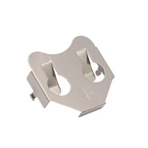
Securing the negative terminal for A, AA, and CR2 cells directly onto a printed circuit board requires rigid pin coplanarity and excellent stress relaxation resistance to withstand wave soldering turbulence. The Jiatel JT-BCKS590L functions as a high-reliability, 1:1 mechanical drop-in alternative for the industry-standard Keystone 590L contact. Built with a 3-pin through-hole design, it removes the need for secondary wire routing and enables direct board-level power installation inside molded battery housings.
Verified Electro-Mechanical Parameters
| Target Cross-Reference | Form-Fit Mechanical Drop-In for Keystone 590L |
| Mating Component | JT-BC-AA-KS596 (Positive Dimple) |
| Mounting Architecture | PCB Through-Hole Mount (THM) |
| PCB Layout Pitch | 10.62±0.30mm Width Spread |
| Dynamic Structure | Compression Leaf Spring |
| Base Metallurgy | T=0.30mm Spring Steel | Nickel Plated |
Target Deployments
- Industrial IoT: PCB-mounted sensor nodes utilizing CR2 cells.
- Medical Diagnostics: Compact patient monitoring devices.
- Consumer Electronics: High-drain tactical lighting PCBA modules.
- Smart Peripherals: Electronic lock logic boards.
Metallurgical Rigidity & Kinematic Stability
To ensure robust polarity engagement and absorb axial cell length variations, the JT-BCKS590L features a precision-stamped compression leaf spring. The main bracket and THM pins are stamped from rigid T=0.30mm Spring Steel. This specific metallurgical gauge guarantees absolute structural rigidity, preventing the contact from tilting or yielding under continuous battery compression forces. The entire assembly is finished with high-density nickel plating, maximizing wave solder wettability and defending against acidic electrolyte fluid leaks.
NPI PCB Footprint Audit & SLA Directive
Board-level integration demands strict adherence to pin pitch and drill hole diameter tolerances (3 x Ø1.40mm) to prevent wave soldering misalignment. Our engineering directive strictly prohibits the deployment of unverified digital mockups for PCB layout confirmation. We execute structural footprint validation exclusively through official [Technical Datasheets] and dimensionally controlled [2D Footprint Specs].
To confirm that our THM negative contact matches your existing FR4 land pattern and plastic compartment constraints, mobilize our Senior NPI Engineering Team. Submit your board-level constraints directly to our technical desk: NPI Engineering Queue. We guarantee the dispatch of matched, production-ready PDF drawings within 12 working hours of form submission.