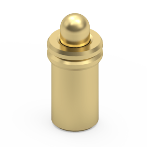
Form-Fit Mechanical Replacement for 8.3mm Extended DIP Pins
Electronic architectures featuring multi-layer stacked boards or elevated component modules require interconnects that provide both extended reach and absolute mechanical retention. The Jiatel 1.8×8.3mm series functions as a 1:1 mechanical drop-in alternative for long-reach legacy through-hole pogo pins. By anchoring directly into the PCB plated through-holes, this extended DIP configuration resists the amplified lateral shear forces inherent in taller interconnects. The 1.0mm compression stroke dynamically absorbs board-to-board co-planarity tolerances across larger physical gaps, ensuring unbroken data and power transmission paths in severe vibration environments.
Verified Technical Metrics
| Mechanical Profile | Ø 1.8mm Barrel | 8.3mm Extended Resting Height |
| Deflection Stroke | 1.0mm Working Travel |
| Electrical Path Capacity | DC 12V / 1.0A to 1.5A Continuous Load |
| Contact Resistance | ≤ 30mΩ Initial Maximum |
| Thermal Profile Resilience | -40°C to +150°C Operational Range |
Target THT Deployments
- Modular Systems: Elevated stacked PCB architectures.
- Industrial Automation: Heavy-duty, large-gap testing fixtures.
- Battery Management: Deep-reach power distribution units.
- Automotive Electronics: Spaced-board internal vehicular routing.
Material Science Under Thermal Extremes
Extended barrel lengths present unique challenges in maintaining internal spring alignment and consistent electrical resistance. To prevent internal binding and signal degradation, the turned plunger and 8.3mm barrel are fabricated from optimized brass alloys protected by a gold-plated layer over a nickel diffusion barrier. This surface engineering maintains the mechanical integrity of the internal spring across 10,000 mating cycles. Explicitly tested to sustain performance up to 150°C, this high-temperature rating prevents pin seizing within dense, multi-layer enclosures.
NPI Footprint Auditing & Verification Queue
Through-hole wave soldering for long-reach components requires strict control over pin pitch and vertical coplanarity to prevent angular tilt and subsequent mating failures. We enforce tight manufacturing tolerances to eliminate insertion errors on multi-layer boards. Our engineering directive strictly prohibits the deployment of unverified digital mockups. Footprint matching and clearance audits are processed exclusively using official [Technical Datasheets] and dimensionally verified [2D Footprint Specs].
To confirm that our 1.8×8.3mm barrel configuration integrates seamlessly into your stacked board layout without causing tilt or hole clearance friction, our Senior NPI Engineering Team executes comprehensive audits. To initiate a cross-reference evaluation and obtain production-ready PDF drawings, submit your terminal layout to our desk: NPI Engineering Queue
SLA Commitment: Upon form submission to our NPI Engineering Queue, we guarantee the dispatch of matched, production-ready PDF drawings within 12 working hours.