
Comprehensive Guide to Pogo Pin Assembly: Process, Key Points, and Innovative Applications
I. In-depth Analysis of Pogo Pin Component Structure

The Pogo Pin, an essential elastic contact electronic component in modern electronic devices, mainly consists of three parts: the plunger, the spring, and the barrel. The barrel usually serves as a stable base, and its material and manufacturing process determine the overall mechanical strength and electrical performance. In terms of material selection, metal alloys with high conductivity and corrosion resistance, such as brass or stainless steel, are often used. They are precisely machined to ensure a smooth inner surface, providing a stable track for the smooth sliding of the plunger. The spring is the core elastic support component. Depending on different application scenarios, its spring constant is carefully calculated and selected. It is made of high-quality alloy steel wire and can maintain stable contact pressure while ensuring the reliability of multiple compression and rebound cycles. The head of the plunger is often designed with a special contact point, such as a spherical or flat shape, to optimize the stability of the electrical connection with the mating part. Its material matches that of the barrel, ensuring conductivity while also considering wear resistance.
II. Detailed Explanation of Diversified Assembly and Connection Processes
(I) PCB Board Soldering (SMT Process)
Struggling with plastic melting during soldering? Our engineers can provide a customized assembly SOP for your project. [Contact Technical Support]

- During the reflow soldering process, the Pogo Pin first needs to be accurately placed on the pre-designed solder pad positions of the PCB board. The surface of the solder pad is usually specially treated, such as being coated with solder paste, to ensure good solder wettability. When the PCB board enters the reflow soldering oven, the temperature curve is strictly set according to the melting and solidification characteristics of the solder paste. In the heating stage, the temperature is gradually increased to enhance the activity of the flux in the solder paste and remove the oxide layer on the soldering surface. After reaching the melting point, the solder paste quickly melts and fills the tiny gaps between the Pogo Pin pins and the solder pads under the action of surface tension, forming a reliable metal alloy connection. In the cooling stage, the cooling rate needs to be precisely controlled to prevent cracks or cold solder joints in the solder joints due to thermal stress. The entire process is completed under the precise control of automated equipment, ensuring the consistency and reliability of each solder joint in large-scale production. It is suitable for electronic products with extremely high requirements for precision and production efficiency, such as the motherboard of a smartphone with high-density PCB assembly.
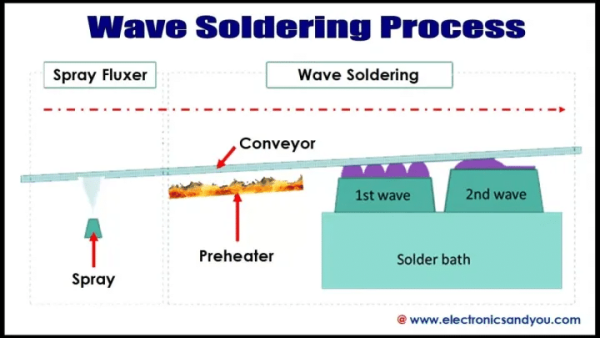
- Wave SolderingWave soldering is suitable for soldering Pogo Pins to the through-holes or specific solder pad areas of the PCB board. The PCB board firstgoes through a flux spraying process, and the evenly coated flux plays a crucial role in cleaning and enhancing the solder wettability in the subsequent soldering process. Subsequently, thePCB board passes through the molten solder wave at a specific angle and speed along the conveyor track. The solder fills the gaps between the Pogo Pin pins and the through-holes or solder pads under the push of the wave, forming a firm connection. Compared with reflow soldering, wave soldering has unique advantages when dealing with larger or irregular PCB boards and Pogo Pin assemblies with higher pin counts. It is commonly used in the manufacturing of industrial control boards, server motherboards, and other electronic products.

(II) Wire Soldering Connection Method


For the wire soldering assembly method, in terms of the operation sequence, the spring pins are usually first fixed in the specific card slots or positioning holes of the plastic parts or PCB board to ensure their accurate and reliable positioning. When soldering the wires, it is necessary to match the appropriate solder according to the materials of the selected wire and the Pogo Pin pins. Commonly used ones are solder wires with a relatively high silver content to ensure good electrical connection performance. The control of soldering time and temperature is the key point. Generally, when using high-temperature solder, the soldering time should be precisely controlled within a few seconds, and the temperature should be maintained within a narrow range slightly higher than the melting point of the solder. If the soldering time is too long or the temperature is too high, the heat will quickly conduct to the plastic parts, causing the plastic to soften or even melt, resulting in the spring pins losing their fixed support and causing the risk of pin loosening or falling off. In some miniaturized or high-density electronic products, such as micro-sensor modules, to avoid the influence of heat on the plastic parts, it is preferred to solder the wires to the connection points of the PCB board and then realize the electrical connection with the Pogo Pin through the internal circuit of the PCB board, effectively isolating the soldering heat and ensuring the stability of the assembly structure.
(III) Elastic Butt Assembly Method
The elastic butt assembly mainly relies on the elastic structure of the Pogo Pin itself to achieve electrical connection without the need for traditional soldering processes. In practical applications, for example, in the design of the connection interface of some quickly detachable electronic devices, the Pogo Pin is installed at the docking port of the device. Through close contact with the mating part and using the elastic pressure of the spring to maintain stable contact. The advantage of this assembly method is that it is convenient for frequent plugging and maintenance of the device, effectively reducing potential failure points caused by soldering. However, it has extremely high requirements for the dimensional accuracy and surface flatness of the Pogo Pin and the mating part. High-precision processing technologies need to be adopted during the manufacturing process to ensure good contact between the two and keep the contact resistance at a low and stable level to meet the electrical transmission performance requirements.
III. Key Points and Coping Strategies in the Assembly Process
(I) Key Points of PCB Soldering
The flatness and dimensional accuracy of the product are directly related to the quality of PCB soldering. In the automated production lines of reflow soldering and wave soldering, the soldering equipment picks up and places the Pogo Pin and PCB board relying on high-precision mechanical structures. If there are tiny bumps or dimensional deviations at the bottom of the product, it will cause problems such as position offset and skew when placed on the PCB board, resulting in uneven distribution of solder and increasing the probability of defective soldering such as cold solder joints and short circuits. To ensure the flatness of the product, strict control of processing parameters is required in the manufacturing process of the Pogo Pin, and surface treatment processes such as precision grinding and polishing are adopted. In terms of dimensional accuracy, high-precision mold forming and testing equipment are used to conduct strict dimensional sampling inspections on each batch of products to ensure that they meet the design standards. In the PCB board design stage, it is necessary to reasonably plan the layout and size of the solder pads, optimize the design according to the shape, spacing, and tolerance range of the Pogo Pin pins, and reserve a certain process margin to compensate for possible manufacturing errors and improve the soldering yield.
(II) Key Points of Wire Soldering
The precise control of soldering time and temperature is the key point of wire soldering. As mentioned above, while high-temperature solder realizes electrical connection, if the heat management is improper, it will easily cause damage to the plastic parts. In addition to strictly controlling the soldering time and temperature, auxiliary heat dissipation measures can also be adopted. For example, a small heat sink can be installed near the plastic parts or a material with good thermal conductivity can be used as the support structure to accelerate heat dissipation and reduce the heating temperature of the plastic parts. In terms of soldering operation skills, operators should receive professional training and be proficient in the use of soldering tools to ensure that the solder melts and wets evenly and forms reliable solder joints. At the same time, after soldering is completed, it is necessary to conduct appearance inspection and electrical performance tests on the solder joints. For example, use a microscope to observe whether the appearance of the solder joints is smooth and free of pores, and use a multimeter to measure whether the connection resistance is within the normal range, so as to timely detect and repair potential soldering defects.
IV. Innovative Applications and Solutions in the Industry

In the field of new energy vehicle charging, with the rapid development of electric vehicle technology, there is an increasing demand for high-voltage and high-current charging. Relying on its 15 years of in-depth technical experience in the Pogo Pin field, CFE has developed an innovative high-voltage and high-current charging pin solution. The Pogo Pin components in this solution have made significant breakthroughs in materials science. New composite materials with high conductivity, high temperature resistance, and anti-electrical corrosion properties are selected to ensure extremely low and stable contact resistance during high-current transmission, effectively reducing energy loss and heat generation. In terms of structural design, the fitting accuracy between the barrel and the plunger is optimized, and a heat dissipation structure design is added. For example, heat dissipation fins are designed on the surface of the barrel or an internal liquid cooling channel technology is adopted to improve the heat dissipation efficiency and ensure the safety and reliability of the charging process. At the same time, CFE provides customers with a one-stop customized Pogo Pin magnetic connection charging solution. By integrating the magnetic adsorption function, the charging interface can achieve automatic alignment and close adsorption during the connection process, greatly enhancing the user’s convenience and injecting new impetus into the innovation and development of new energy vehicle charging technology, promoting the industry to move towards an efficient and intelligent charging new era.

In the field of consumer electronics, the rise of TWS (True Wireless Stereo) earphones has put forward requirements for miniaturization and high performance of Pogo Pins. To meet the needs of the compact internal space of the earphones and stable charging and signal transmission, ultra-small Pogo Pins have emerged. The diameter of the barrel can be reduced to a few millimeters, and the spring is specially treated to provide stable elastic force in a very small space, ensuring that the earphones are tightly connected to the charging interface in the charging case, realizing fast charging and stable audio signal transmission, and enhancing the user experience. For example, Apple’s AirPods series products adopt customized Pogo Pin components, and their exquisite manufacturing process and optimized design ensure the reliability during frequent use of the earphones, becoming an industry model.

In the field of medical electronic devices, hearing aids are one of the important application scenarios of Pogo Pins. Due to the small size of hearing aids and the need for long-term wearing, there are strict requirements for the stability and biocompatibility of Pogo Pins. Medical-grade Pogo Pins use special hypoallergenic materials to make the outer shell to ensure safe contact with human skin. Their internal structures are carefully designed to achieve efficient electrical connection in a limited space, providing stable support for the micro-battery charging and signal processing modules of the hearing aids, helping hearing-impaired patients to hear the world clearly, reflecting the key role and technical value of Pogo Pins in the medical field.


