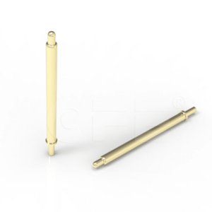
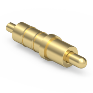
High-Retention Through-Hole Pogo Pin for Robust PCB Architectures
We engineer this 1.6mm diameter, 7.0mm length Through-Hole (DIP) pogo pin designed for mission-critical board-to-board interconnections. Our manufacturing matrix optimizes the tail geometry with an integrated positioning pin for high-strength mechanical anchoring and seamless wave soldering processes. Our test data shows sustained electrical continuity (1A, < 30mΩ) under severe mechanical shock and vibration, making it a reliable 1:1 drop-in alternative to legacy Keystone or Mill-Max through-hole contacts in space-constrained yet rugged environments.
Verified Technical Metrics
| Dimensions (Diameter x Length) | Ø 1.6mm x 7.0mm |
| Stroke & Spring Force | Nominal: 1.0mm | Recommended: 1.5mm @ 20gf±10gf |
| Electrical Specification | 5V / 1A per contact |
| Contact Resistance | < 30mΩ Maximum |
| Mechanical Life | 10,000+ Cycles (Minimum) |
Target DIP Applications
- Industrial Automation: High-vibration testing equipment.
- Medical Devices: Rugged patient monitoring systems.
- Automotive: In-car sensors and navigation modules.
- Telecommunications: Base station interconnects.
Plating Integrity & Environmental Resistance
To maintain sub-30mΩ resistance across 10,000+ mating cycles, we deploy a thick gold-over-nickel plating matrix. Specifically, the contact surfaces utilize Brass Au3μ” over 50-80μ” Ni, while the SUS304 spring features Au1μ” plating. The nickel underlayer prevents copper migration and hardens the contact surface against friction, guaranteeing zero contact oxidation across a rigorous -30°C to 85°C thermal profile.
Strict Tolerance Controls & Engineering Support
Precision hardware integration requires exact pin spacing and tail diameter controls to prevent displacement during PCB soldering. We strictly prohibit the distribution of unverified digital mockups. Instead, our process pivots entirely toward rigorous tolerance verification based on official [Technical Datasheets] and verified [2D Footprint Specs].
To guarantee flawless through-hole assembly, we deploy our Senior NPI Engineering Team to audit your PCB constraints and ensure a 1:1 precision replacement. We enforce a strict 12-hour fast response SLA. To secure your position in our technical validation pipeline, route your layout parameters directly to our desk: Request Engineering Support
SLA Commitment: Upon form submission to our NPI Engineering Queue, we guarantee the dispatch of matched, production-ready PDF drawings within 12 working hours.