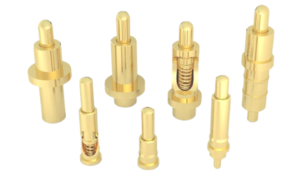
Why Nickel Underplating Is Critical for Gold-Plated Pogo Pins & Connectors
A Technical Selection Guide for Hardware Engineers
1. Introduction: The Hidden Flaw in “Gold-Plated” Connectors
Here’s a scenario every hardware engineer dreads: your pogo pin connectors pass initial QA with flying colors—low contact resistance, clean mating, beautiful gold finish. Six months into field deployment, however, your wearable device starts reporting intermittent connection failures. The gold plating looks intact. So what went wrong?
Industry data tells a sobering story: Among pogo pin failures recorded after 100,000 mating cycles, an estimated 70% are attributable to the absence of a proper nickel underplating layer. The gold surface is not the problem—the invisible foundation beneath it is.
The core misconception: Gold plating ≠ high reliability. A connector that skips nickel underplating may appear cost-efficient on a BOM, but it carries three latent failure mechanisms—metal diffusion, galvanic corrosion, and mechanical collapse—that silently accumulate until the system fails.
2. The Hidden Failure Risks: What Happens Without Nickel?
2.1 Metal Diffusion Failure — The Silent Killer
Copper (the base material) atoms are restless at elevated temperatures. Without a nickel barrier, copper atoms migrate upward through the thin gold layer via solid-state diffusion. The consequences are severe:
- Copper oxides form at the contact surface, drastically increasing resistance.
- In tin-plated connectors, copper migration creates Cu&₆Sn&₅ and Cu&₃Sn Intermetallic Compounds (IMCs), destroying solderability and promoting tin whisker growth, causing short circuits.
Quantified impact: Contact resistance can rise from an initial 5 mΩ to over 50 mΩ after 100,000 cycles without a barrier layer.
2.2 Galvanic Corrosion — The Environmental Accelerant
Thin gold deposits (<10μ”) are inherently porous. When moisture penetrates these pores to reach the copper substrate, a galvanic cell forms. The large electrochemical potential difference between Copper (−0.34V) and Gold (+1.50V) drives aggressive localized pitting corrosion.
Nickel’s standard electrode potential (−0.25V) is far closer to copper, making it an electrochemically compatible intermediate material that seals pores and stops galvanic decay.
3. The 4 Core Engineering Benefits of Nickel Underplating

3.1 The Diffusion Barrier (Supressing IMCs)
The dense nickel crystal lattice acts as a molecular firewall, physically impeding the thermally-activated diffusion of copper atoms. To be effective, the thickness must meet specific industry standards:
| Application Tier | Nickel Thickness (μ”) | Standard Reference |
|---|---|---|
| Minimum Functional Barrier | 50μ” (1.27μm) | MIL-C-26074, IPC-4552 |
| Standard Industrial | 50–80μ” (1.27–2.03μm) | ASTM B689 |
| High-Reliability / Medical | 80–100μ” (2.03–2.54μm) | Automotive / Medical Grade |
3.2 Environmental Shielding & Porosity Sealing
Electrodeposited sulfamate nickel exhibits extremely low porosity. A 50μ” nickel layer effectively seals the micro-pores inherent in a 10–30μ” gold top coat. This dual-layer system guarantees Jiatel’s connectors pass ≥48 to 96 hours in ASTM B117 Salt Spray Tests with zero base metal exposure.
3.3 Mechanical Support & Wear Resistance (The “Anvil” Effect)
Pure gold is extremely soft (20–40 HV). Under repeated compressive forces, unsupported gold deforms plastically. Nickel’s Vickers hardness (150–250 HV) provides a rigid mechanical foundation. For high-cycle applications, hard gold over nickel delivers exponentially better wear performance than thick soft gold alone.
| Material | Vickers Hardness (HV) | Role in Plating Stack |
|---|---|---|
| Copper Substrate | 80–120 HV | Base conductivity & mechanical structure |
| Soft Gold (99.9%) | 20–40 HV | Low-resistance contact surface |
| Hard Gold (Co/Ni Alloy) | 130–200 HV | Wear-resistant contact surface |
| Nickel Underplating | 150–250 HV | Mechanical support & wear barrier |
3.4 Enhanced Plating Adhesion
Direct gold-on-copper plating is prone to delamination under thermal cycling (e.g., automotive −40°C to +125°C) due to expansion mismatch. Nickel acts as an exceptional adhesion promoter, bonding fiercely to both the CuTe substrate and the precious metal finish.
4. Jiatel’s Optimized Plating Stack & Real-World Case
Understanding the theory is essential, but executing it in production defines quality. All Jiatel gold-plated products ship with a minimum 50μ” nickel underplating layer as standard.
Case Study: Wearable Magnetic Charging Contacts
Challenge: Original supplier’s pogo pins (no nickel spec) degraded from 8 mΩ to 65 mΩ after 50k cycles. Field return rate: 3.2%.
Jiatel Solution: Implemented a 75μ” sulfamate nickel / 20μ” hard gold stack on CuTe substrate.
Results: Resistance stabilized at 8.5 mΩ after 120,000 cycles. Passed 96h salt spray. Field return rate dropped to <0.1%.
5. Practical Selection Guide for Engineers
Use this reference table to specify your connector diffusion barrier plating accurately on your next BOM:
| Application Scenario | Recommended Ni Thickness | Top Plating Match | Key Performance Criteria |
|---|---|---|---|
| Consumer (TWS/Wearables) | 50 – 60μ” | Flash Gold 5–10μ” | Cost efficiency, lightweight |
| Industrial Test Fixtures | 70 – 90μ” | Hard Gold 15–25μ” | 100K+ cycles, wear resistance |
| Medical / Automotive | 80 – 100μ” | Hard Gold 25–30μ” | Long-term stability, thermal cycling |
| PCB SMT Soldering | 50 – 80μ” | Tin or SnAg | Solderability, RoHS compliance |
Critical Pitfalls to Avoid:
- Too Thin (<30μ”): The barrier fails. Pinholes allow copper migration within the first 20,000 cycles. Do not accept “nickel flash” as a substitute.
- Too Thick (>120μ”): Excessively thick deposits introduce internal compressive stress, leading to plating brittleness and micro-cracking during crimping.
- Mismatched Plating Chemistry: Decorative bright nickel (high internal stress) is unsuitable for high-reliability connectors. Improper bath chemistry causes poor adhesion and high porosity. Always specify engineering-grade sulfamate nickel.
6. Conclusion
Nickel underplating is not an “optional” feature for high-quality connectors—it is the mandatory foundation for reliability. While gold plating determines the initial performance, the nickel barrier layer dictates long-term survival against diffusion, corrosion, and wear.
Ready to Optimize Your Connector Plating Stack?
Don’t let improper plating specifications cause field failures. Jiatel engineers provide step-by-step support, ensuring your connectors meet strict MIL and ASTM standards.
- Technical Consultation: Get a Free DFM Design Review to define the exact nickel/gold ratio for your project.
- Prototyping: Request Free Samples of our nickel-gold plated Pogo pins (shipped via DHL/FedEx) for your own impedance testing.